Download the notes from the link below:
Download the same notes in grey background color effect and in less file size, from 2nd link below:
The topics included in this notes are:
1. Armature Reaction
a) Armature Reaction effect due to purely Resistive load (Unity Power Factor Load)
b) Armature Reaction effect due to purely Inductive load (Zero Power Factor Lagging Load)
c) Armature Reaction effect due to Practical load (RL Load, with more Inductive)
d)Armature Reaction effect due to purely Capactive load (Zero Power Factor Leading Load)
2. Representing Armature Reaction Effect:
a) Voltage drop due to imaginary Armature Reaction
b) Voltage drop due to Leakage Flux (Reactance of Armature)
c) Voltage drop due to Resistance of Armature Conductor
3. Per Phase Equivalent Circuit of an Alternator
4. Voltage Regulation.
5. Load characteristics of an alternator.
6. Determination of Voltage Regulation by Mathematical Approach
a) For Lagging Load
b) For Leading Load
c) For Resistive Load
7. Determination of Voltage Regulation by Direct Loading
8. Voltage Regulation for Large rating Alternators:
a) Synchronous Impedance Method or EMF Method
i) Open Circuit Test of Alternator
ii) Short Circuit Test of Alternator
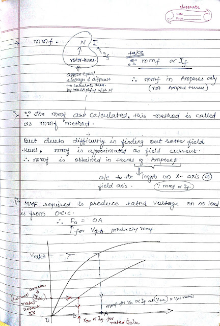
b) Ampere Turns Method ( AT Method) or MMF Method
i) For Zero Lagging Load
ii) For Zero Leading Load
iii) For Resistive Load
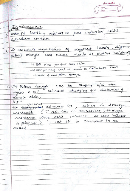
c) ZPF (or Zero Power Factor Method) or Potier Triangle Method
d) ASA Method ( American Standard Association Method)
9. Comparison between Direct Loading, EMF, MMF, ZPF and ASA method of Voltage Regulation
10. Short Circuit Ratio (SCR) of an Alternator.
Download the notes from the link below:
Download the same notes in grey background color effect and in less file size, from 2nd link below:
Download the same notes in grey background color effect and in less file size, from 2nd link below:
The topics included in this notes are:
1. Armature Reaction
a) Armature Reaction effect due to purely Resistive load (Unity Power Factor Load)
b) Armature Reaction effect due to purely Inductive load (Zero Power Factor Lagging Load)
c) Armature Reaction effect due to Practical load (RL Load, with more Inductive)
d)Armature Reaction effect due to purely Capactive load (Zero Power Factor Leading Load)
2. Representing Armature Reaction Effect:
a) Voltage drop due to imaginary Armature Reaction
b) Voltage drop due to Leakage Flux (Reactance of Armature)
c) Voltage drop due to Resistance of Armature Conductor
3. Per Phase Equivalent Circuit of an Alternator
4. Voltage Regulation.
5. Load characteristics of an alternator.
6. Determination of Voltage Regulation by Mathematical Approach
a) For Lagging Load
b) For Leading Load
c) For Resistive Load
7. Determination of Voltage Regulation by Direct Loading
8. Voltage Regulation for Large rating Alternators:
a) Synchronous Impedance Method or EMF Method
i) Open Circuit Test of Alternator
ii) Short Circuit Test of Alternator
b) Ampere Turns Method ( AT Method) or MMF Method
i) For Zero Lagging Load
ii) For Zero Leading Load
iii) For Resistive Load
c) ZPF (or Zero Power Factor Method) or Potier Triangle Method
d) ASA Method ( American Standard Association Method)
9. Comparison between Direct Loading, EMF, MMF, ZPF and ASA method of Voltage Regulation
10. Short Circuit Ratio (SCR) of an Alternator.
 |
| page 1a |
 |
| page 1b |
 |
| page 2a |
 |
| page 2b |
 |
| page 3a |
 |
| page 3b |
 |
| page 4a |
 |
| page 4b |
 |
| page 5a |
 |
| page 5b |
 |
| page 6a |
 |
| page 6b |
 |
| page 7a |
 |
| page 7b |
 |
| page 8a |
 |
| page 8b |
 |
| page 9a |
 |
| page 9b |
 |
| page 10a |
 |
| page 10b |
 |
| page 11a |
 |
| page 11b |
 |
| page 12a |
 |
| page 12b |
 |
| page 13a |
 |
| page 13b |
 |
| page 14a |
 |
| page 14b |
 |
| page 15a |
 |
| page 15b |
 |
| page 16a |
 |
| page 16b |
 |
| page 17a |
 |
| page 17b |
 |
| page 18a |
 |
| page 18b |
 |
| page 19a |
 |
| page 19b |
 |
| page 20a |
 |
| page 20b |
 |
| page 21a |
 |
| page 21b |
 |
| page 22a |
 |
| page 22b |
 |
| page 23a |
 |
| page 23b |
 |
| page 24a |
 |
| page 24b |
 |
| page 25a |
 |
| page 25b |
 |
| page 26a |
 |
| page 26b |
 |
| page 27a |
 |
| page 27b |
 |
| page 28a |
 |
| page 28b |
Download the notes from the link below:
Download the same notes in grey background color effect and in less file size, from 2nd link below:
